Signal Generator Module Waveform Generators 01Hz Circuit Diagram So after the first op amp, we have a square waveform. What follows next is an integrator circuit. When you feed a square waveform into an integrator circuit, the output is a triangle waveform. So after the second op amp, we now have a triangle waveform, as our second waveform. We then feed this triangle waveform into another integrator circuit. This function generator a.k.a waveform generator can produce square wave (5V/0V) with frequency ranging from 1Hz to 2MHz, the frequency of the wave can be controlled by a knob and the duty cycle is hardcoded to 50% but it is easy to change that in the program as well. Apart from that, the generator can also produce since wave with frequency
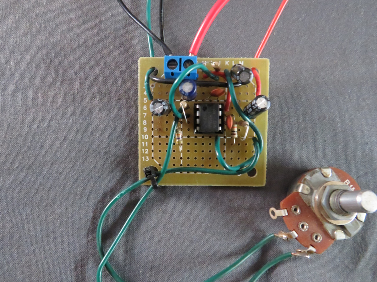
As a hobbyist, it is a fun and easy project to test and hone your skills using Arduino. For testing - when you are creating a circuit, testing a piece of equipment (i.e. an amplifier) or testing a frequency response, it is useful to have one handy to inject the signal into the circuit or device. Building the signal generator. 1 This IC 741 based function generator circuit delivers increased test versatility compared to the typical sine wave signal generator, giving 1 kHz square and triangle waves together, and it is both low-cost and very simple to construct. As it appears the output is approximately 3V ptp on square wave, and 2V r.m.s. in the sine -wave.
DIY Waveform Generator using Arduino Circuit Diagram
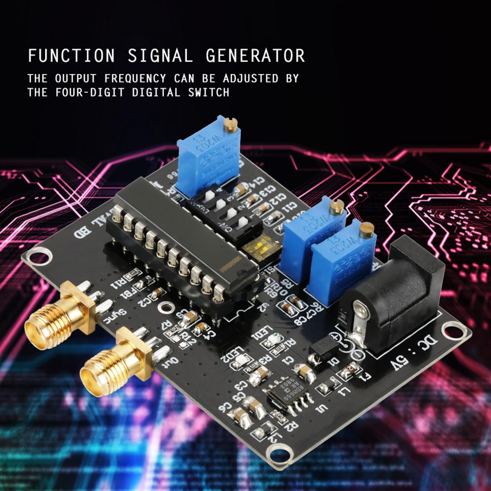
Through analysis, devise your own signal generator, capable of generating following waveforms of desirable amplitude and frequency: 1. Square wave (bonus for varying duty cycle) 2. Sine Wave 3. Sawtooth Wave The signal generator design should include the capability to adjust signal frequency and amplitude. It is a DDS type programmable waveform generator, so it takes a clock signal with a maximum frequency of 25MHz (for this particular IC), which it then divides based on a value passed by the microcontroller (maximum 2 28) via the SPI bus, and using a 10-bit DAC it outputs a waveform chosen by the microcontroller. The output has a peak-to-peak

DIY Function/Waveform Generator: In this project we will have a short look at commercial function/waveform generators in order to determine what features are important for a DIY version. Afterwards I will then show you how to create a simple function generator, the analog and digit… A Function generator , often known as Wave-form generator is a circuit that produces a variety of different wave-forms at a desired frequency. Function generator is one of the important devices in laboratory when it comes to generating electrical waveforms like sine, triangle,square or pulses over a range of frequencies, amplitude and duty cyle.

Learn to Generate Electrical Signals Circuit Diagram
Need to test circuitry but don't have a waveform generator? A DIY signal generator that measures arbitrary waveforms is easy and affordable to make using the PBB-272C powered breadboard and a few other tools. To create our analog function generator circuit, we will use a 555 timer to create a sine wave signal.